Benutzer-Werkzeuge
Importing manholes, links and catchments from shapefiles
⯇ Back to Importing manholes and links from Excel
Continue to Import according to 'Digital Sewer Cadastre' ⯈
Menu item: Tools > Import and Export
Page valid for MIKE+ 2021
Introduction
The import of network data into MIKE+ works via the import-export interface. This interface allows you to make the necessary mappings between the shape source files and the target tables in MIKE+ with the help of a user interface. This tutorial explains how to import using an import file (*.xml).
Setting up and performing the import
To perform the import, download the Import configuration file. If you like, you can try out the import using example-shape-files. Unzip both files into any folder.
Source shapefiles
The import configuration file "IMPORT_from-shp-with-catchments_v03.xml" is based on three external shapefiles:
- Nodes_v03.shp: NODEID, GROUNDLEV, BOTTOMLEV
- Links_v03.shp: CROSSECT, HEIGHTMM, WIDTHMM
- Catchments_v03.shp: NR, MANHOLE, AREAM2, ROOFM2, STREETM2
When importing to MIKE+, the data is written to the following tables:
- Nodes (msm_Node)
- Links (msm_Link)
- Catchments (msm_Catchment)
- Catchment connections (msm_CatchCon)
Job with data source
Create an new database for "Rivers, collection systems and overland flows" and keep local coordinates.
Go to Tools > Import and Export. The editor has two panels, the job panel on the left side and the table configuration panel on the right side. We start with the job.
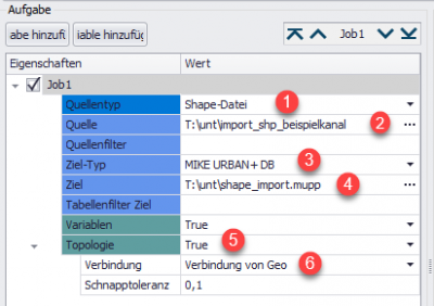
(1) Shape file is the default source type. The drop-down reveals additional options.
(2) Under source, specify the path to the folder containing the shapefiles.
(3) The default "Target type" is "MIKE+ DB".
(4) Normally, the current MIKE+ database becomes target automatically. Hover over the path to check the full path and the database.
(5) Set "Correct topology" to "Yes".
(6) For "Connectivity", select "Connection from Coordinates". This is necessary for MIKE+ to create a correct topology when importing from shapefiles.
Open import specification
(1) In the "Tools" menu…
(2) …open the import-export interface.
(3) Load the "import_ausshp.xml" with the specific settings for this shape file import.
Table Configuration for Nodes
The table configuration defines the assignments between the data sources (shapefiles) and the MIKE+ tables.
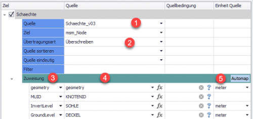
(1) Under "Source" select the shapefile "Nodes_v03", which is one of the shapefiles available in the specified directory. Target refers to the table within the MIKE+ database, in our case msm_Node.
(2) The transfer mode determines how the import deals with already existing data. In our case, Overwrite the data.
For the nodes we'll add assignment by assignment manually.
(3) Click <Insert assignment>.
(4) The drop-down in the second column shows all attributes from Nodes_v03.shp. Choose NODEID
(5) The names of the target MIKE+ attributes are in the first column. Choose MUID.
Repeat steps 3 to 4 for GROUNDLEV, BOTTOMLEV and geometry. Attribute Geometry makes sure that the coordinates from the shapefile, whether point, line or polygon shapefile, are transferred to MIKE+.
With the above import configuration, the Nodes in MIKE+ would show errors, as the mandatory attribute "Diameter" is empty. Instead of using the field calculator to provide the required value, we can already during import assign a fixed value to all nodes.
(6) Insert an assignment, select "Diameter" and open the Expression editor [fx]
with the
The fifth assignment is a bit special.
Setting the table configuration Links
(1) The procedure for the links (msm_Link) is similar. The height, width and diameter are specified in mm in the shape file. If the MIKE URBAN database has been created with the unit system "SI-m3_per_second", the diameter, height and width are given in m. The right-hand field "Unit" is therefore used. Therefore, the right field "Unit Source" is adjusted.
(2) For the profile type, source conditions have been defined to take into account the different profiles (circular, rectangular, egg, special). (In MIKE+ these profile types are identified by attribute domains; a number behind which is the exact definition / description. For example, TypeNo = 1 stands for a circular profile).
Setting the table configuration catchment areas
(1) The geometry of the polygon is taken over with the assignment "geometry" = "geometry".
(2) The MUID of the catchment area is called "NR" in the shapefile.
(3) For this import, the fields of the hydrology data for model A are filled. Therefore, the Hydrolgic Model Time-Area (A) must be assigned for all catchments. Since this field is stored in the database using domains, the assignment is set to "1" for model A.
(4) To determine the imperviousness of the individual catchments, the paved area (= roof and road areas) is divided by the total area of the catchment.
(5) "-DEFAULT-" is assigned as the parameter set. This parameter set can subsequently be adapted in MIKE+.
Defining the table configuration catchment area links
(1) The catchment area ID is again used as CatchID: NR
(2) The catchment areas are linked to individual nodes. This designation is hidden behind domain 1. The ID of the assigned manholes is "NODES".
![]() Attention! In the MIKE+ 2020 version there is still a display error when importing the catchment area links. The catchment area links are imported correctly and the associated allocation works correctly, but they are not yet displayed correctly.
Attention! In the MIKE+ 2020 version there is still a display error when importing the catchment area links. The catchment area links are imported correctly and the associated allocation works correctly, but they are not yet displayed correctly.
Check and execute the import
Finally, use (1) "Check" to run a diagnostic of the upcoming import. If all assignments are correct, an "OK" appears in the lower right corner (2) of the import interface:
(3) Now carry out the import using Start.
Results
To check the imported sewer network, switch to the map view. The imported network should correspond to the following image.
To check the imported attributes, select the configuration table of the nodes, for example. The values in the attribute table should correspond to those in the shape file.
Technical details
Table Configuration Node
| target | source | source condition | unit source |
|---|---|---|---|
| geometry | metre | ||
| MUID | NODEID | ||
| InvertLevel | SOHLE | Meter | |
| GroundLevel | LID | Meter |
Table configuration links
| target | source | source condition | unit source |
|---|---|---|---|
| geometry | Meter | ||
| TypeNo | 1 | PROFILE == 'circle' | |
| TypeNo | 2 | PROFILE == 'special profile' | |
| TypeNo | 3 | PROFILE == 'Rectangular profile' | |
| TypeNo | 5 | PROFILE == 'Egg' | |
| Length | LENGTH | Meter | |
| Diameter | HEIGHT | Millimetre | |
| HEIGHT | HEIGHT | Millimetre | |
| Width | WIDTH | Millimetres |
Table configuration catchment areas
| target | source | source condition | unit source |
|---|---|---|---|
| geometry | |||
| MUID | NR | ||
| HydrologicalModelNo | 1 | ||
| ModelAImpArea | ( [DACHM2] + [STRASSEM2] )/ [FLAECHEM2] | ||
| ModelAParAID | "-DEFAULT-" |
Table configuration catchment areas
| Target | Source | Source Condition | Source Unit |
|---|---|---|---|
| CatchID | NR | ||
| TypeNo | 1 | ||
| NodeID | KNOTES |


