Benutzer-Werkzeuge
Inhaltsverzeichnis
MIKE View Instability Result
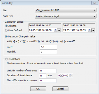
Menue: Tools > Comupte > Instability
Manual: MIKE View User Guide, Water Distribution User Guide, section 10.1 Computing Derived Items
Page last modified: with MIKE View 2024
This page was written with major input from Stanislav Vanecek (SV).
Introduction
In MIKE View instability is a derived item of a pipeflow result file (*.prf or *.res1d). The tool performs an analysis based on the criteria specified in the dialog.
- Elements exceeding the criterion are considered as unstable and get a value of 1.
- All other elements get a value of 0, which means that the element doesn't indicate an instability.
The assigned values are not time series, but each element gets a single value.
There are two main approaches to compute instability:
- Maximum change in value
- Oscillations
Instability can be derived for various result items, like node water level or link velocity, and then displayed in the map.
Dialogue
| Field | Description |
|---|---|
| File | Result file |
| Data type | Result item within the chosen result file |
| Calculation period | Either the entire result file, or a user defined period within |
| Maximum Change in Value | |
| coeff | Maximum relative change in value |
| maxdiff | Maximum absolute change in value |
| Oscillations | |
| Limit for number of extremes | If the number of extreme values is equal to or greater than this limit, the element is marked as unstable. |
| Duration of time interval | Defines the extent of the movable/floating time window for counting extreme values. |
| Min difference for extremes | Filters very small instabilities |
Usage
(1) Open result file.
(2) Tools > Compute > Instability
(3) Fill in parameters, then click <OK>.
(4) Click <OK>, if want to write a list of unstable elements, then specify the result file name (including the extension .txt). Click <Cancel> if you want to proceed without a text file. Here is an example for such a text file:
Maximum change
=================
Coeficient : 0.100
Min. Difference: 0.000
Tested interval :whole simulation
Instability Links - Velocity
================
10262001C (10262001_MS2 -> 10264909)  28.45
10266004 (10266004 -> 10266047)  5.00
10266013 (10266013 -> 10266047)  5.00
10268006 (10268006 -> 10268005)  5.00
10268025 (10268025 -> 10268508)  5.00
(5) Open the Horizontal Plan Options, choose the instability result from the bottom of the drop down list, and click <OK>:
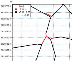
(6) The Horizontal Plan shows the unstable elements (value = 1) in red, and the stable elements (value = 0) in black:
Technical Details
Maximum Relative Change in Value
If the relative change from one time step to the next is larger than coeff at any time step in the calculation period, then the model element will be marked as instability.
In the above example the criterion is a 0.1 = 10 % relative change. Set maxdiff = 0 in order to deactivate evaluation of absolute change.
Note that the equations here define instability and use a ">" sign, whereas in the MIKE View interface the equations define stability and use a "<".
Maximum Absolute Change in Value
If the absolute change from one time step to the next is larger than maxdiff at any time step in the calculation period, then the model element will be marked as instability.
In the above example the criterion is a 0.02 absolute change. If applied to the link velocity this would be a change of 0.02 m/s compared to the last time step. Set coeff = 0 in order to deactivate evaluation of relative change.
Maximum Relative and Absolute Change in Value
If only those elements should be marked as instability which meet both relative and absolute criteria, fill in both values. The number of elements marked unstable will be smaller than if the criteria are used separately.
Oscillations
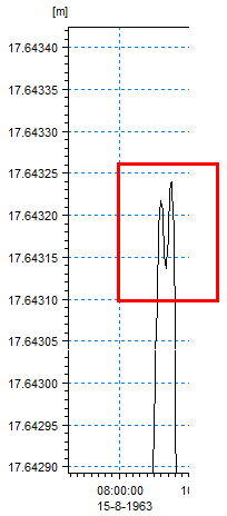
Oscillations are measured by the number of local maxima or minima. The figure below shows 3 extreme values.
Limit for number of extremes defines how many oscillations should be considered as instability. If in the above example the limit would be 1 or 2, then 1 or 2 extreme values would be considered as normal. If the limit is set to 3, any element with 3 or more extreme values is considered as unstable, and hence gets marked with value 1.
Duration of time interval defines the extents of the movable/floating time window. It is moved from one saving time step to the next. Extremes are evaluated/counted for each window.
Time and date format follows the Windows Settings.
If duration of the interval is zero (days + hours), the floating window is the full simulation interval (or user-defined calculation period), and all local extremes are counted.
Min. difference for extremes filters very small instabilities (i.e. due to value rounding, etc.). In case shown below, if the minimum difference of extremes = 0.002, only one extreme will be counted. If minimum difference of extremes = 0, 3 extremes will be counted.
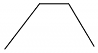
If the local extreme is “locally constant”, see below, and the duration of the interval is bigger than length of this constant period, only one extreme is counted. The tool does not count the values on the other time steps (i.e. flat/constant period) as extreme values.
Open Issues
- Does the tool work with result files of type *.res11?
- What about the "Instability test" in the horizontal plan's context menue?


